PNEUMATIC SYSTEMS
Introduction
When speaking about pneumatic system, we need to speak about where the pneumatic system comes from and it comes from a power system, there are three different types of power systems,
- Hydraulic system
- Pneumatic system
- Electrical system
Pneumatic systems in Aircrafts
Pneumatic systems they are besides known as vacuity or force per unit area systems, the power many maps which are of import to the aircraft. Power instrument set downing cogwheel, flaps, Windowss, air conditioning, doors and car pilot devises are some of many operations powered by pneumatic system. Pneumatic and hydraulic systems are similar and usage tight fluids. Fluid belongings could be liquids as H2O, oil, or something that flows. And both liquids and gases flow, since they are considered as fluids ; nevertheless, there is a great trade of difference in the features of the two.
Liquids can non be compressible ; a quart of H2O still occupies about a quart of infinite regardless of how difficult it is compressed. But gases can be compressed, a quart of air can be compressed into a thimbleful of infinite. Sing this differences gases and liquids are fluids and can be made to convey power. The type of unit used to supply pressurized air for pneumatic systems is determined by the system’s air force per unit area demands.
Components in Pneumatic System
Hydraulic systems are sometimes compared to, pneumatic systems but some similarities can merely be true in general footings. Such as
Pneumatic systems do non
- utilize reservoirs
- manus pumps
- collectors
- regulators
- constructing normal force per unit area from engine or electrically goaded power pumps
But similarities do be in some constituents.
Air Compressors
Simply an air compressor is a Pump that compresses air, its occupation is raising air force per unit area to above established force per unit area for usage in pneumatic systems on some aircraft, air compressors have for good installed and added to reload air bottles when force per unit area is used to run a unit. Several types of compressors that are used for this intent. Some have three phases of compaction, while the others have two, depending on the desired operating force per unit area.
Relief Valves
Relief valves are used to forestall harm. They act as a force per unit area restricting units and prevent bursting lines and blowing out seals from inordinate force per unit areas.

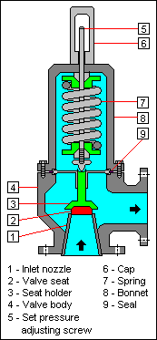
Control Valves
Control valves are besides a necessary portion of a typical pneumatic system. It is used to command conditions such aspressure, flow, temperature, andliquidlevel by to the full or bit by bit opening or shutting. Control Valve is besides called a Final Control Element.

Check Valves
Check valves are used in both hydraulic and pneumatic systems. Check valve is besides called a one manner valve which allows pressurized air to come in the system, but it prevents backflow of air toward the Compressor when Compressor system is stopped which prevent loss of force per unit area in the system.

Restrictors
Restrictor is type of control valve used in pneumatic system. Figure below 1llustrates an opening type restrictor which has a big recess port and a little mercantile establishment port. The rate of the air flow and the velocity of operation of the triping unit will be cut down by the little mercantile establishment port.

Variable Restrictor
The variable restrictor is a type of velocity modulating unit it contains an adjustable needle valve, hence has threads around top and the lower terminal. Depending on the way turned and the needle valve turns the crisp point either into or out the little gap to diminish or to increase the size of the gap. Since air come ining the recess port must be able to go through through this gap before making the mercantile establishment port accommodation determines the rate of air flow through the restrictor.

PRESSURE REGULATOR
The force per unit area regulator is to command the maximal force per unit area in the system and to off-load the compressor when the system is idle.
Oil and Water Trap regulator
The oil and H2O trap is designed to take any H2O or oil which may be suspended in the air delivered by the compressor.

Air Filters
Air filters purpose is to forestall oil vapour, soil or wet from go throughing into the assorted services. It is installed vertically with the drain stopper at the underside.
Some advantages are
- Prevent system taint
- Remove air particulates
- Clean air is indispensable to good operation

Figure 1. Position of Cutaway air filter. Air come ining the top of subdivision first flows through the component to take solid atoms. Then flows in a round gesture, where centrifugal force offprints H2O from the air watercourse, andthen the H2O falls to the filters sump.
Storage Bottles
Storage bottles act as a reservoir of compressed air which operates all services to pneumatic system. Compressors chief usage is to construct up system force per unit area when it falls below normal force per unit area degree. The size of the bottles are taken from the volume of actuators and grapevines determines required for the normal and exigency pneumatic services.
Storage bottles are by and large made of steel, and may utilize a wire lesion building for maximal strength. Light ally or fiberglass stuffs may be other typs of stuff wich will be used.

Air Pump
Heart of pneumatic system is force per unit area or vacuity air pump. Which is normally engine driven )
There are two basic types: •Wet air pumps which use engine oil to lubricate pump internally
•Dry air pumps which is more common more common have graphite vanes inside pump casing self-lubricate as pump rotates

High force per unit area systems
High force per unit area system is driven by an engine driven compressor provenders air from an unloading valve through the system maintaining the force per unit area. The force per unit area around this system is 3000 pounds per square inch but this will change from maker to another. There will normally besides be a land valve on the aircraft system to enable to supercharge when the chief engines are non running. In high force per unit area systems air is usually stored in a metal bottles at force per unit areas from 1000-3000 pounds per square inchs, depending on the peculiar aircraft system.
Some high force per unit area systems are
- Oxygen lines
- Flaps
- Interruptions
- Landing cogwheel
Low force per unit area systems
Low force per unit area systems are pressurized up to 1000 pounds per square inch and uses an engine driven vane type pump. They are may be used to drive
- Air cons
- door seals
- de-ice boots
- little low power applications
Medium-Pressure Systems
A medium-pressure pneumatic system normally does non include an air bottle. Alternatively, it draws air from the compressor subdivision of a turbine engine. Which is by and large about 50 to 150 pounds per square inch This is frequently called bleed air procedure and is used to supply pneumatic power for engine starts, engine deicing, flying deicing, and in some instances, it provides hydraulic power to the aircraft systems but merely if the hydraulic system is equipped with an air-driven hydraulic pump. Engine bleed air is besides used to supercharge the reservoirs of the hydraulic system.
Emergency Backup Systems
Many aircraft use a high force per unit area pneumatic back up system beginning to widen the landing cogwheel or trip the brakes. And if chief hydraulic braking system fails. Nitrogen gas is non straight used to trip the landing cogwheel or brake system units but applies the pressurized N to travel hydraulic fluid to the actuator. This procedure is called pneudraulics.
Nitrogen Bottles
There are two bottles of N stored for exigency usage, largely bottles located on each side of nose wheel good. Actuation of an mercantile establishment valve released by Nitrogen from the bottles. Once depleted, care forces must reload the bottles. Fully serviced force per unit area will be about 3,100 pounds per square inchs at 70 °F/21 °C, which is merely plenty for one extension of the landing cogwheel.
PNEUMATIC SYSTEM
The illustrator below is a typical full pneumatic system as is used on a duplicate engine commuter conveyance aircraft.
Each process is shown below in point points
- Each of the two compressors is a four phase Piston type pump, driven from the accoutrement gear box of the two propjet engines.
- Air is taken into the first phase through an air canal.
- It is compressed, so passes to the other three phases.
- From the 4th phase the discharge air is routed through an intercooler and a bleed valve to the unloading valve.
- The bleed valve is kept closed by engine oil force per unit area and in an event of a loss of an engine lubricating oil, the valve will open and alleviate the pump of any burden.
- The unloading valve maintains force per unit area between 2,900 and 3,300 pounds per square inch in the system.
- When the force per unit area rises to 3,300 pounds per square inchs a cheque valve traps it and dumps the end product of the pump air overboard.
- The pump is directed back into the system when the system force per unit area drops to 2,900 pounds per square inchs.
- The bird valve which is between the compressor and the chief system makes it possible to bear down the system from a land beginning.
- When the force per unit area from the external beginning is higher than the external beginning of the compressor, when the engine is non running, the bird slides over and deep-freezes the compressor.
- Compressed air system have wet and this will distill and stop dead when the force per unit area of the air is dropped for propulsion because of this every spot of H2O must be removed from the air.
- Then a centrifuge collects the H2O that is in the air on a baffle and holds it until the system is shut down.
- When the separator’s force per unit area drops below 450 pounds per square inchs, a drain valve operates and all of the accrued H2O is blown overboard.
- Then an electric warmer prevents the H2O collected in the centrifuge from stop deading.
- After the air leaves the wet centrifuge, approximately 98 % of its H2O removed, it passes through a drying agent, or chemical desiccant, to take the last hints of wet.
- Before the air enters the existent operating system it is filtered through a 10 micrometer sintered metal filter.
- In the right engine nacelle a back force per unit area valve is installed.
- This is basically a force per unit area alleviation valve in the supply line that does non open until the force per unit area from the compressor or land bear downing system is above 1700 pounds per square inch and this brand sure that the wet centrifuge will run most expeditiously.
- The left side where there is no back force per unit area valve can be connected if it is required to run the system from an external beginning of less than 1700 pounds per square inch.
- There are three air storage bottles in this type of aircraft system,
- A 750 copper. Inch bottle for the chief system
- A 180 copper. Inch bottle for normal brake operation
- A 180 copper. Inch bottle for exigency operation of the landing cogwheel and brakes.
- Then come the reciprocally operated isolation valve which allows a technician to shut off the air supply so that the system can be serviced without holding to dispatch the storage bottle.
- Most of the constituents in this system run with force per unit area of 1000 pounds per square inchs so a force per unit area cut downing valve is installed between the isolation valve and the supply manifold for normal operation of the
- set downing cogwheel
- rider door
- retarding forces brake
- propellor brake
- nose wheel maneuvering
- Since this valve reduces the force per unit area to 1000 pounds per square inch it besides serves as a backup force per unit area alleviation valve.
- The exigency system shops compressed air under the full system force per unit area of 3,300 pounds per square inchs and supplies it for set downing gear exigency extension.
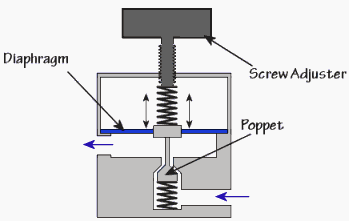
EMERGENCY BRAKE SYSTEM
In a failure of the hydraulic system, the pilot of a big aircraft can run a pneumatic valve on the instrument panel and direct compressed air or N into the brake system. When the pilot turns the grip, a regulator is adjusted that controls the air force per unit area to the brakes. When sufficient force per unit area reaches the brake line, the Piston moves up against the force of the control spring and close off the recess valve. The compaction of the spring determines the sum of force per unit area supplied to the brake. When the brake grip is rotated in the way to let go of the brakes, the air is exhausted overboard.
Then instead than leting tight air to come in the wheel cylinder, which would necessitate the full brake system to be bled of air, the exigency air may be directed into a transportation tubing. The air forces hydraulic fluid from the tubing into the brake system.
Emergency operation of the brakes is besides achieved in many aircraft by the usage of tight air. When the pilot is certain that there is no hydraulic force per unit area to the brakes, the pneumatic brake grip, located on the left instrument panel, can be rotated. Clockwise rotary motion of this grip increases the brake force per unit area. Nitrogen force per unit area released by this control grip forces hydraulic fluid in the transportation tubing into the chief wheel brakes through shuttle valves. When the brake grip is rotated anticlockwise force per unit area is released and the N is exhausted overboard.
hypertext transfer protocol: //www.engineerstudent.co.uk/uni_directional_flow_control_valve_symbols.html
hypertext transfer protocol: //navyaviation.tpub.com/14018/css/14018_285.htm
hypertext transfer protocol: //en.wikipedia.org/wiki/Relief_valve
hypertext transfer protocol: //mech-engineer.blogspot.com.au/2009/05/drawworks-brake-system-training-course.html
hypertext transfer protocol: //www.aliexpress.com/airbrush-compressor-regulator_reviews.html
hypertext transfer protocol: //www.airid.com/high-volume-drain-valve.html
hypertext transfer protocol: //basicaerospace.blogspot.com.au/2013/01/aircraft-pneumatic-system-for-beginners.html